In the article "Memory Paging Using MSX-DOS 2", we explained how to request 16K RAM pages from MSX-DOS2 and place code into those blocks so it could be executed by the Z80. The main drawback is that the C modules you compile must follow a memory layout that is not easy to achieve. You need to perform several calculations to determine where each block will be placed and how it should be defined so that SDCC can resolve it correctly. Another solution is to abandon MSX-DOS2 altogether and switch to the ROM cartridge format. Instead of storing data on a floppy disk, everything is stored in the cartridge ROM, providing much faster access.
This update revises the explanation of variables and memory segments to make it easier to understand.
As we have explained in previous articles, the Z80 can address a maximum of 64K, divided into four 16K pages. To overcome this limitation, the MSX standard introduced a system of 16K slots and subslots, allowing the memory visible to the Z80 to be changed by assigning different slots to each page. Typically, page 0 is occupied by the BIOS, page 1 and 2 by one of the cartridge slot, and page 3 by RAM. Depending on the manufacturer, however, the BIOS and RAM may be located in different slots and subslots.
If you insert a 16K cartridge into the first cartridge slot, the Z80 will see those 16K mapped into page 1. As larger ROMs became necessary, mappers were introduced. These are ROMs larger than 16K, divided into multiple segments, with additional hardware logic that dynamically switches which segments are visible in each of the Z80's memory pages. These mappers were never standardized, and different manufacturers developed their own implementations, such as ASCII-8, ASCII-16, Konami5, and others.
The MSXgl library supports programming for several mapper types. In this article, we will use the ASCII-8 mapper, where each segment is 8K in size. This mapper is also described in the MSXgl documentation.
To take advantage of the ROM creation features provided by the MSXgl library, the following parameters must be enabled in project_config.js:
Target = "ROM_ASCII8";RawFiles = [ { segment: 10, file: "./content/img/PatBosc.sc5" },
{ segment: 15, file: "./content/img/PatBosc.pl5" }
];RawFiles section contains all binary files that do not need to be compiled, such as images or sound files, and can be placed directly into the ROM.
MSX-DOS2 provided memory paging functions to allocate and switch memory pages. With MSXgl, ROM memory segments can be managed using the following functions:
SET_BANK_SEGMENT(u8 page, u8 number_of_segment): Loads the ROM segment number_of_segment into the Z80 memory page specified by page.GET_BANK_SEGMENT(u8 page): Returns the number of the segment currently mapped into the specified Z80 memory page.An example of these functions in use can be found in the file squirrel.c, where we call a function located in one of the ROM segments:
189void obtenir_coordenades_rajola(char map_x, char map_y) {
190  u8 savedSeg = GET_BANK_SEGMENT(3);
191  SET_BANK_SEGMENT(3, 6); // El segment del mapa squirrel_s6_b3
192  char tipus = map1[map_x + (map_y * NOMBRE_RAJOLES_HOR)];
193  stamp_x = (tipus % NOMBRE_RAJOLES_HOR_ORIGEN_PATRONS) * 8;
194  stamp_y = OFFSET_COORDENADAY_PAGINA_ACTIVA_1 + (tipus / NOMBRE_RAJOLES_HOR_ORIGEN_PATRONS)*8;
195  SET_BANK_SEGMENT(3, savedSeg);
196}
First, we save the segment currently mapped into the memory page that we want to replace with the new segment (this may not be necessary if your program structure always uses the same mapping, but doing so makes the code more generic). Next, we map ROM segment 6 into MSX memory bank 3. In our project structure, this segment corresponds to squirrel_s6_b3, which the MSXgl project generation script has already placed in the correct location when building the ROM.
The map1 variable is a constant located in the segment we have just activated, so line 192 retrieves the correct value. It is very important to declare such variables using the extern directive to indicate that they are not defined in the current C file and that the linker is responsible for placing them at the correct memory address.
Finally, on line 195, we restore the memory mapping that was active before switching segments to access map1.
In this example, we only switched memory to access a large variable, but the same technique can also be used to call an entire function located in another ROM segment and then return to the original one. The more self-contained a function is (that is, the fewer global variables it accesses and the fewer external functions it calls), the better suited it is for placement in an independent segment.
Another interesting operation is how images are loaded from the ROM into the VDP. Previously, we loaded them from disk, but how do we now access the part of the ROM where MSXgl has placed them? The following code performs this operation:
200void ROM_LoadSc5Image() {
201  u16 dst = 0x8000;
202  u16 file_size = 33792;  // PatCit.sc5 is 33KB
203  u16 bytes_loaded = 0;
204  u8 segment;
205  u8 savedSeg = GET_BANK_SEGMENT(3);
206
207  // Load PatCit.sc5 from segments 5-9 (spans 5 segments of 8KB each)
208  for (segment = 10; segment <= 14 && bytes_loaded < file_size; segment++) {
209    SET_BANK_SEGMENT(3, segment);
210    const u8 *src = (const u8 *)0xA000;
211
212    u16 size_to_copy;
213    if (bytes_loaded == 0) {
214      // First segment: skip 7 bytes header
215      src += 7;
216      size_to_copy = (file_size < 8185) ? file_size - 7 : 8185;
217      bytes_loaded = size_to_copy;
218    } else {
219      // Subsequent segments: copy full 8KB or remaining bytes
220      size_to_copy = (file_size - bytes_loaded < 8192) ? (file_size - bytes_loaded) : 8192;
221      bytes_loaded += size_to_copy;
222    }
223
224    VDP_WriteVRAM(src, dst, 0, size_to_copy);
225    dst += size_to_copy;
226  }
227
228  SET_BANK_SEGMENT(3, savedSeg);
229}
The dst variable is the VRAM address where we want to start writing. file_size is the size of the file in bytes, which can easily be determined using ls -l on Linux or the file properties in other graphical environments. bytes_loaded is a counter that keeps track of how many bytes have been copied and is used to load the remaining bytes from the last segment. On line 205, as before, we save the currently mapped segment so that it can be restored after the loading process is complete. We then enter the loop on line 208. How do we know which segments to read and how many there are? The answer is simple: in our project_config.js file we defined the following:
147//-- List of raw data files to be added to final binary (array). Each entry must be in the following format: { offset=0x0000, file="myfile.bin" }
148RawFiles = [
149	{ segment: 10, file: "./content/img/PatBosc.sc5" },
150	{ segment: 15, file: "./content/img/PatBosc.pl5" }
151];
This indicates that the file PatBosc.sc5 starts at ROM segment 10. Knowing that the total file size is 33,792 bytes, we can calculate how many segments are required: 33792 / (8 × 1024) = 4.125. This means the file occupies four complete segments plus part of a fifth one. Therefore, the loop must iterate through segment 14, where the fifth and final segment contains only the remaining bytes.
The if statement on line 213 simply skips the first 7 bytes of the file, which contain file header information rather than VRAM data. On line 220, we check whether the remaining bytes to load correspond to a full segment (8 × 1024 = 8192 bytes) or just the remaining portion of the last segment. The data is then copied from ROM to VRAM using the VDP_WriteVRAM function. Finally, once the loop has finished, we restore the original segment mapped into bank 3.
In this section, we will discuss several techniques for programming with memory segments while avoiding overwrite errors or making such errors easier to detect.
This is a critical aspect and requires careful planning from the beginning. The goal is to create segments that are as self-contained as possible, avoiding references to variables or functions located in other segments. In a complex application, this is often difficult to achieve. Therefore, it is best to keep variables shared by multiple segments in the fixed bank that is never remapped. The same applies to functions: utility functions used by multiple segments should also reside in the fixed bank. This makes it much easier to ensure that they are always accessible during execution.
We must keep in mind how SDCC works. It creates a global variable pool, so all variables declared as extern are visible to every segment at compile time.
With the ASCII-8 mapper, only four banks are available for the program itself. Other mappers, such as NEO, remove the dedicated Main ROM area, allowing up to six programmable banks.
If a segment exceeds its maximum size, part of the generated code will not be placed correctly. During compilation, MSXgl displays a message similar to the following:
┌───────────────────────────────────────────────────────────────────────────┐
│ PACKAGE                                                                   │
└───────────────────────────────────────────────────────────────────────────┘
Packaging binary...
Execute: "/home/jepsuse/MSX/MSXgl/tools/MSXtk/bin/MSXhex" /home/jepsuse/MSX/MSXgl/projects/learning-msxgl/2p_squirrelHunt/out/squirrel.ihx -e rom -s 0x4000 -l 131072 -b 8192  -f /home/jepsuse/MSX/MSXgl/projects/learning-msxgl/2p_squirrelHunt/out/msxhex.txt
Log: Add file './content/img/PatBosc.sc5' at offset 00014000h
Log: Add file './content/img/PatBosc.pl5' at offset 0001E000h
MSXhex 1.0.0 - Convert an Intel HEX file to binary
Start=00004000h Size=00020000h Bank=00002000h Pad=FFh
Saving /home/jepsuse/MSX/MSXgl/projects/learning-msxgl/2p_squirrelHunt/out/squirrel.rom...
Seg[0000]: Lower=4000h Higher=8A20h Size=18977 (Holes=0)
Seg[0004]: Lower=A000h Higher=ABC5h Size=3014 (Holes=0)
Seg[0005]: Lower=A000h Higher=A04Ah Size=75 (Holes=0)
Seg[0006]: Lower=A000h Higher=BAFFh Size=6912 (Holes=0)
Total size: 28978
Exit code: 0
Success
Here we have a list of the segments that make up our project. Since we are using the ASCII-8 architecture, each segment is 8,192 bytes in size. Our application begins with segment 0, whose code spans more than two segments, so banks 0, 1, and 2 are already occupied. This is why, in the previous examples, we placed our additional functions in bank 3. The remaining segments—4, 5, and 6—are all smaller than 8K, so none of them overlap and there is no risk of corrupting the application.
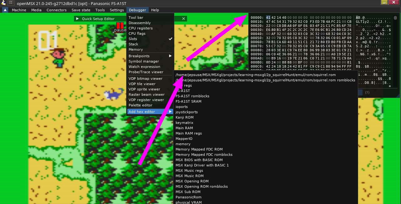
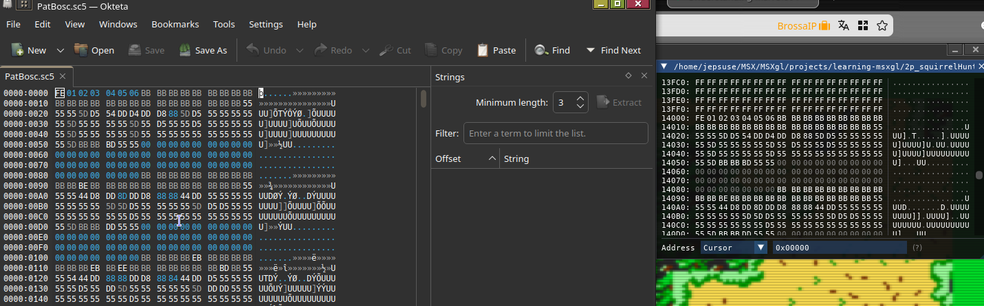
If you want to verify that the ROM loaded by openMSX is correct, open the debugger and select Add Hex editor. Your ROM file will appear, allowing you to inspect its binary contents. To verify that MSXgl has correctly placed the raw files into the ROM, compare the address shown in the debugger with the original binary file. For example, we load PatBosc.sc5 into segment 10, so it should begin at offset 10 × 8 × 1024 = 0x14000 in the ROM. Comparing the contents in the debugger with a hex editor such as Okteta shows that they match, as illustrated in the following image:
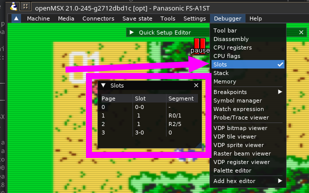
Another useful openMSX debugger is the Slot Viewer, which shows, for each Z80 memory page, which slot is currently mapped. Since we are using 8K segments, each 16K Z80 page consists of two ROM segments. openMSX displays this information using the notation RX/Y, where X is the first segment and Y is the second. Thus, in our application, as shown in the image below, Z80 page 1 contains ROM segments 0 and 1, while page 2 contains segments 2 and 5. This fourth segment, segment 5, is the one we dynamically switch depending on which part of the program requires it. If you let the application run, you will see this value constantly changing, for example from 5 to 6 and to other segment numbers.